
In recent years, new energy vehicles have developed rapidly in China. Because of its high efficiency, energy saving, low noise, no pollution, etc., it has become a new trend in the development of the automobile industry at home and abroad. Although the power, drive, and control systems applied to new energy vehicles are not much different from industrial applications in theory, they are extremely important in terms of safety, stability, and reliability under different working conditions. High requirements, which makes electric vehicles more comprehensive and serious considerations in the circuit design and the selection of the components used. As the battery management system of the power part of electric vehicles, its safety, reliability, and stability are undoubtedly the key to the performance of the whole vehicle. This article makes the following analysis and discussion on the selection of precharge resistors in the battery management system.
What is a precharge resistor? Simply put, the power supply must charge the capacitor at the beginning of power-on. If it is not limited, the charging current will be too large, which will cause a greater impact on the relay, rectifier device and the capacitor to be charged, so the resistor is used to limit the current. The resistor used here is Precharge resistor.
The battery management system of new energy vehicles will involve high-voltage pre-charging. This is because the motor controller (that is, the inverter we often call) has a large bus capacitance. In the case of cold start without pre-charging, if the main relay is directly connected, the high voltage of the battery will be directly loaded on the empty bus capacitor, which is equivalent to an instant short circuit, and a large instant current will damage the relay. After adding the pre-charging resistor, the bus capacitor is pre-charged through the pre-charging circuit, so that the current when the main circuit is turned on can be controlled within a safe range to ensure the normal operation of the system.

We can learn from the above introduction that the precharge resistor is an indispensable and critical component in the battery management system. So how should we analyze and choose the appropriate resistor for this application?
Before resistance selection, we must first clearly understand the operating conditions and parameter requirements, which are summarized as follows:
High-voltage battery power supply output voltage
Rated current
Bus capacitance value
Maximum possible ambient temperature at startup
Requirement of resistance temperature rise
Capacitor pre-charging place Required voltage
The time required to reach the charging voltage
Single pulse or continuous pulse?
If it is a continuous pulse, what is the number of times the resistance can resist the continuous pulse and the pulse interval?
When the battery is abused, the resistance is required to maintain the normal working state for the duration of time
Installation structure and wiring method of the resistance
Requirements for insulation voltage
After understanding the detailed working conditions and parameters, you need to do some basic calculations. Normally, the pre-charging is required to be completed within 500ms. In such a short time, the high heat generated by the current passing through the resistance wire or the resistance body cannot be absorbed by the resistance skeleton, and the resistance wire or the resistance body itself will have to bear the huge burden. Part of the pulse energy. So we must first calculate the pulse energy at start-up, and then choose the appropriate resistance scheme.
If it is a single pulse, the energy is calculated as follows:

If it is a continuous pulse, when the pulse interval is very short (for example, less than 1s), the proportion of energy dissipated in practical applications is very small, we can generally use linear Accumulate to calculate the total pulse energy.
Total Energy=single pulse energy x number of continuous pulses
Then determine the resistance of the precharge resistor:
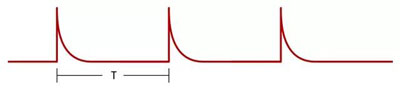
T = RC * Ln[(Vbat-V0)/( Vbat-Vpre )]
where: T=precharge time
R=precharge resistance
C=load-side capacitance
Vbat=battery Package voltage
V0=Voltage before the load terminal is closed and high voltage (can be expressed as 0)
Vpre=Load terminal voltage at the end of precharge
Generally speaking , Vpre is selected to be 90% or 95% of the total voltage Vbat, which is considered to be 90% here, so the formula can be expressed as follows:
T = RC * Ln10 Then R = T / (C * Ln10)< /p>Example analysis: If the total voltage is 700V, the load capacitance C is 2000uF, the maximum precharge time is set to 300ms, when the capacitor voltage reaches 95% of the power supply voltage, the energy of a single pulse is
E = 1/2CV2 ;= 442J If it is 5 consecutive pulses in a short time, the total pulse energy is about E total= 442*5